|
Jinan Sanyisan International Trading Co., Ltd
|
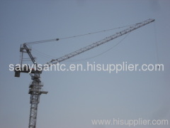
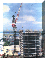
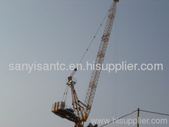
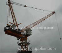
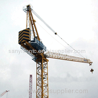
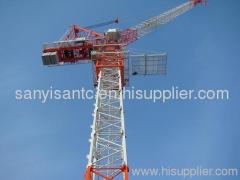
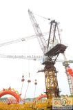
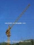
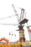
Inner Climbing Tower Crane QTG20 (TC3065) max load 2t
| Price: | 22222.0 USD |
| Payment Terms: | T/T,L/C |
| Place of Origin: | Shandong, China (Mainland) |
|
|
|
| Add to My Favorites | |
| HiSupplier Escrow |
Product Detail
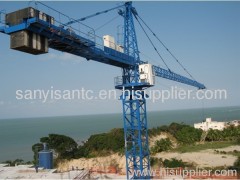
QTG20 inner climbing tower crane:
Max. Load: 2t
Tip load: 0.65t
Jib length: 30m
Free standing height: 19.8m
Inner climbing tower crane
QTG20 inner climbing tower crane:
Max. Load: 2t
Tip load: 0.65t
Jib length: 30m
Free standing height: 19.8m
Inner climbing tower crane jacking
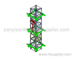
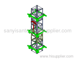
Inner climbing tower crane has three attached frames, from down to up respectively are load bearing attached frame, antirotation attached frame and transition attached frame. The distance between two adjacent attached frames is nine to twelve meters, three attached frames all are on the girder Steel, and they connect with the girder Steel by bolts. The girder Steel is put on the concrete beam of core tube elevator hoistway, and they connect with each other by bolts to assure that connection of girder steel and building structure is reliable. All attached frames can be dismantled to assure the cycle use and function conversion. Load bearing attached frame is mainly to bear the vertical-down acting force generating in every kind of working condition. Antirotation attached frame is mainly to bear the torsional moment and bending moment generating in every kind of working condition, and serve as the climbing pathway in the process of climbing and at last it serves as antirotation attached frame. Tower crane only uses load bearing attached frame and antirotation attached frame to fix tower body in normal working condition, but before climbing we need to install the third attached frame to serve as transition attached frame, so as to assure the reliability of climbing track. Climbing height is the distance between load bearing attached frame and antirotation attached frame.
1\Fix two pieces of ready-made girder steel to concrete beam of building's core tube by sixteen bolts, then install strengthen attached frame on the girder steel and adjust the gap between guide pulley and tower body(generally two to five millimeters). Note: The armoured concrete beam of building must be designed by designing institute and up to the requirement of bearing capacity.
2\Fix the jib in the direction of vertical to climbing crossbeam and adjust the range of trolley to make the barycenter of tower crane pass jacking oil cylinder.
3\Put the claw hand of inner climbing jacking crossbeam on inner climbing pathway, raise the tower body up, and put claw hand of inner climbing base section on vertical position. Figure (1); Put the claw hand of inner climbing base section level, limiting tower body sliding down, draw back jacking oil cylinder. Figure (2); After jacking oil cylinder is drawn back, put the claw hand of inner climbing jacking beam level, and put the claw hand of inner climbing base section vertical. Figure (3); Repeat it again and again to make tower body rise as desired requirement. Figure (4). When tower crane rises to desired height, lay two load bearing support square beams under the channel steel of inner climbing base section, let them bear the weight of tower crane.
| Rated lifting moment | KN· M | 200 | ||||
| Max lifting weight | t | 2 | ||||
| Working radius | m | 2.5-30 | ||||
| Hoisting height | Independence | m | 25.6 | |||
| Hoisting speed | Two maganification | m/min | 26.4/6.3 | |||
| Four maganification | ||||||
| Slewing speed | r/min | 0.76/0.38 | ||||
| Trolleying speed | m/min | 22.5 | ||||
| Jacking speed | ||||||
| Mini steady falling speed | < 7 | |||||
| Outside dimension of whole crane | Chassis | m | 3.847× 3.847 | |||
| The height of crane | Independence | 35 | ||||
| Attachment | ||||||
| From boom end to slewing center | ||||||
| From tail of balance arm to slewing center | 8.4 | |||||
| The whole weight | Structure weight | Independence | t | 10.838 | ||
| Attachment | ||||||
| Balanced weight | 3.470 | |||||
| The total volume of electric motor | kw | 15.6 | ||||
| Allowed working temperature | Degree | -20~+40 | ||||
| The index of power supply | 60Hz | ~380V± 10% | ||||
Related Search
Find more related products in following catalogs on Hisupplier.com
Related Products
-
6 Ton Cable Tension Stringing Equipments with German Rexroth Hydraulic pumpSA-YQ60 SA-YQ90 SA-YZ30A SA-YZ2X35

-
6 Ton Cable Tension Stringing Equipments with German Rexroth Hydraulic pumpSA-YQ60 SA-YQ90 SA-YZ30A SA-YZ2X35


